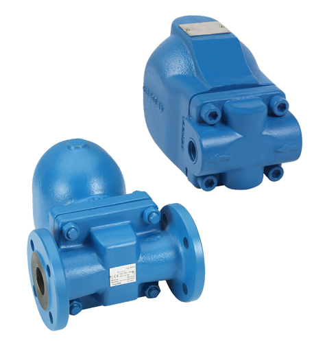
FLOAT STEAM TRAP SCREW END / FLANGED ADCA FLT 17

Material:
nodular Iron EN-JL1030Dimensions:
1/2" - 2"GENERAL DESCRIPTIONS
The ball float mechanism guarantees the direct discharge of condensate. The automatic air vent ensures the discharge of non-condensing gases. The ball float steam trap is designed for horizontal installation. A version for vertical stallation is available upon request. The ball float steam trap is designed for a maximum differential pressure of 4,5 bar. To drain the condesate from steam lines
OPERATION
The (nodular) cast iron float steam traps with a special float mechanism guarantee a direct discharge of large quantities of condensate. The automatic air vent ensures the discharge of non-condensable gases.
MEDIA
Steam.
OPTIONS
SLR (Steam Lock Release) version
Adjustable needle valve
Internal strainer screen
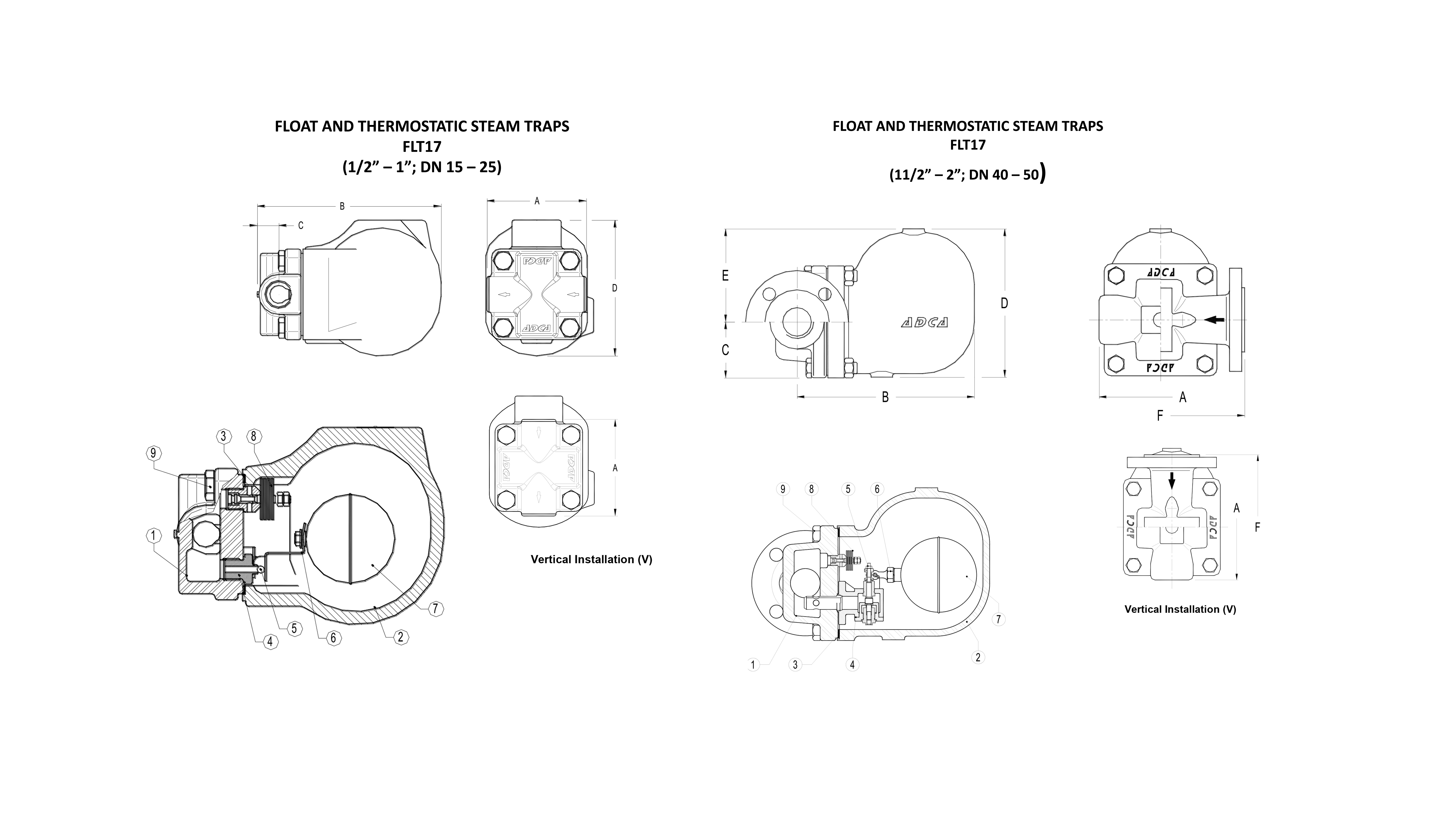
Horizontal installation with the flow from left to right
Vertical installation with the flow from top to bottom

Materials
| N° | POSITION | MATERIALS |
|---|---|---|
| 1 | Body | nodular iron GJS-400-15 / 0.7040 |
| 2 | Cover | nodular iron GJS-400-15 / 0.7040 |
| 3 | Cover sealing | stainless steel / graphite |
| 4.1 | Seat DN15 - DN25 | stainless steel AISI 410 / 1.4006 |
| 4.2 | Seat DN40 - DN50 | stainless steel CF8 / 1.4308 |
| 5.1 | Disk | stainless steel AISI 440C / 1.4125 |
| 5.2 | Disk | stainless steel AISI 420C / 1.4021 |
| 6 | Rod | stainless steel AISI 304 / 1.4301 |
| 7 | Float | stainless steel AISI 304 / 1.4301 |
| 8 | Thermostatic air release | stainless steel (bimetal) |
| 9 | Bolt | steel 8.8 |
Characteristics
| SPECIFICATION | |
|---|---|
| Standard | DIN |
| Connection standard | threaded BSPP / flanged EN1092-2, ANSI 150 |
| Cap connection | bolted |
| Construction | straight |
| Actuation | automatic |
| Air release | automatic |
| Max. differential pressure | 4.5 ; 10 ; 14 Bar |
| Mounting | horisontal / vertical |
Dimensions
| FLOW CAPACITY (kg/h) | |||||||||||||||||
|---|---|---|---|---|---|---|---|---|---|---|---|---|---|---|---|---|---|
| MODEL | SIZE | DIFFERENTIAL PRESSURE (bar) | |||||||||||||||
| DN | 0,1 | 0,3 | 0,5 | 0,7 | 1 | 1,5 | 2 | 3 | 4,5 | 6 | 7 | 8 | 9 | 10 | 12 | 14 | |
| FLT17-4,5 | 15 - 25 | 165 | 205 | 230 | 280 | 330 | 400 | 440 | 535 | 630 | - | - | - | - | - | - | - |
| FLT17-10 | 15 - 25 | 110 | 130 | 150 | 170 | 200 | 250 | 280 | 340 | 400 | 460 | 495 | 520 | 550 | 595 | - | - |
| FLT17-14 | 15 - 25 | 80 | 100 | 120 | 140 | 150 | 190 | 220 | 260 | 320 | 380 | 400 | 425 | 440 | 480 | 510 | 550 |
| MODEL | SIZE | DIFFERENTIAL PRESSURE (bar) | |||||||||||||||
| DN | 0,1 | 0,3 | 0,5 | 0,7 | 1 | 1,5 | 2 | 4,5 | 7 | 10 | 12 | 14 | |||||
| FLT17-4,5 | 40 - 50 | 1050 | 1750 | 2400 | 2700 | 3400 | 3900 | 4500 | 7300 | - | - | - | - | ||||
| FLT17-10 | 40 - 50 | 650 | 1100 | 1500 | 1700 | 2000 | 2600 | 3000 | 4000 | 5400 | 6200 | - | - | ||||
| FLT17-14 | 40 - 50 | 430 | 720 | 950 | 1100 | 1300 | 1600 | 1800 | 2600 | 3250 | 3900 | 4210 | 4950 |
