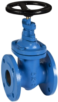
GATE VALVE NON-RISING STEM F4 DIN EN 1171 (DIN 3352 T2)

Material:
cast iron EN-JL1040Dimensions:
DN-40-700DESCRIPTIONS
Gate valves are stop valves and are widely used in industry and shipbuilding.
They are mainly used in systems that transport water or other liquid fluids, including fuels and toxic products, seawater and hydraulic oils.
MEDIA
Water, fuels, lubricating and hydraulic oils, sea water and other.
OPTIONS
· With possition indicator · Without possition indicator · Different materials of the internal parts (trim)
Materials
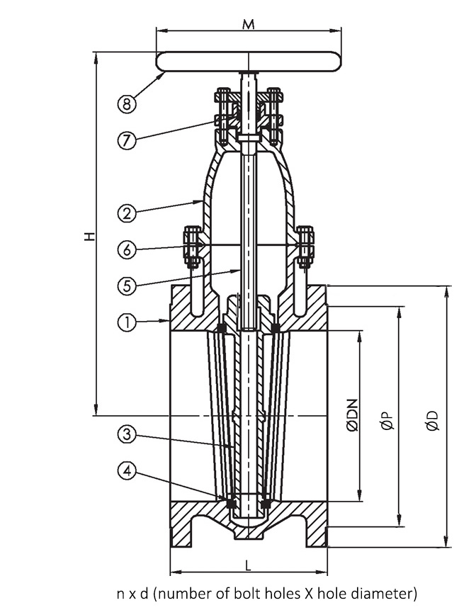
| No. | PARTS | MATERIALS |
|---|---|---|
| 1 | Body | cast iron EN-JL1040 (GG25) |
| 2 | Bonnet | cast iron EN-JL1040 (GG25) |
| 3 | Gate | cast iron EN-JL1040 (GG25) |
| 4 | Seat | st.steel 1.4301 (AISI304) |
| 5 | Stem | st.steel 1.4021 (AISI420) |
| 6 | Bonnet gasket | EPDM aramid |
| 7 | Gland packing | teflon/PTFE |
| 8 | Handwheel | cast iron EN-JL1040 (GG25) |
Characteristics
Dimensions
| DN | PN | Flange/PN | H | L | ØD | ØP* | n x d | Ø M | (kg) | ||||||
|---|---|---|---|---|---|---|---|---|---|---|---|---|---|---|---|
| PN6 | PN10 | PN16 | PN6 | PN10 | PN16 | PN6 | PN10 | PN16 | |||||||
| 40 | 10 | 6/10/16 | 255 | 140 | 130 | 150 | 150 | 100 | 110 | 110 | 4x14 | 4x18 | 4x18 | 125 | 10 |
| 50 | 10 | 6/10/16 | 270 | 150 | 140 | 165 | 165 | 110 | 125 | 125 | 4x14 | 4x18 | 4x18 | 150 | 12 |
| 65 | 10 | 6/10/16 | 323 | 170 | 160 | 185 | 185 | 130 | 145 | 145 | 4x14 | 4x18 | 4x18 | 175 | 17 |
| 80 | 10 | 6/10/16 | 355 | 180 | 190 | 200 | 200 | 150 | 160 | 160 | 4x18 | 8x18 | 8x18 | 175 | 22 |
| 100 | 10 | 6/10/16 | 405 | 190 | 210 | 220 | 220 | 170 | 180 | 180 | 4x18 | 8x18 | 8x18 | 200 | 27 |
| 125 | 10 | 6/10/16 | 460 | 200 | 240 | 250 | 250 | 200 | 210 | 210 | 8x18 | 8x18 | 8x18 | 200 | 33 |
| 150 | 10 | 6/10/16 | 518 | 210 | 265 | 285 | 285 | 225 | 240 | 240 | 8x18 | 8x22 | 8x22 | 225 | 43 |
| 200 | 6 | 6/10/16 | 608 | 230 | 320 | 340 | 340 | 280 | 295 | 295 | 8x18 | 8x22 | 12x22 | 225 | 65 |
| 250 | 6 | 6/10/16 | 708 | 250 | 375 | 395 | 405 | 335 | 350 | 355 | 12x18 | 12x22 | 12x26 | 250 | 100 |
| 300 | 6 | 6/10/16 | 818 | 270 | 440 | 445 | 460 | 395 | 400 | 410 | 12x22 | 12x22 | 12x26 | 300 | 142 |
| 350 | 4 | 10 | 997 | 290 | 505 | 460 | 16x22 | 400 | 207 | ||||||
| 400 | 4 | 10 | 1087 | 310 | 565 | 515 | 16x26 | 400 | 246 | ||||||
| 500 | 4 | 10 | 1308 | 350 | 670 | 620 | 20x26 | 500 | 416 | ||||||
| 600 | 2.5 | 10 | 1493 | 390 | 780 | 725 | 20x30 | 500 | 624 | ||||||
| 700 | 2.5 | 10 | 1780 | 430 | 895 | 840 | 24x30 | 600 | 870 | ||||||
| Remark: dimensions in column ØP, are indicating bolt circle diameter of the connection flanges. |
